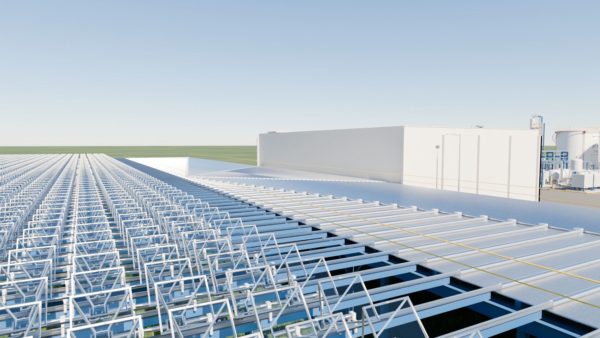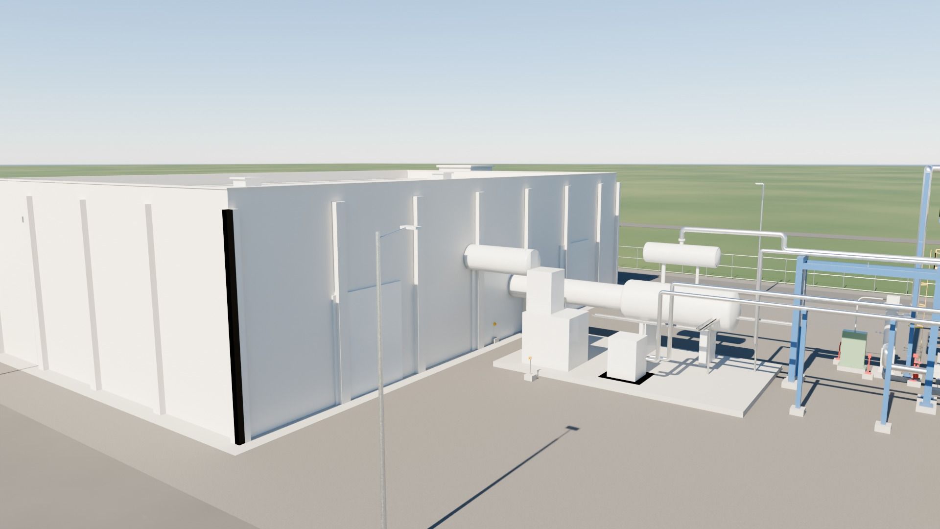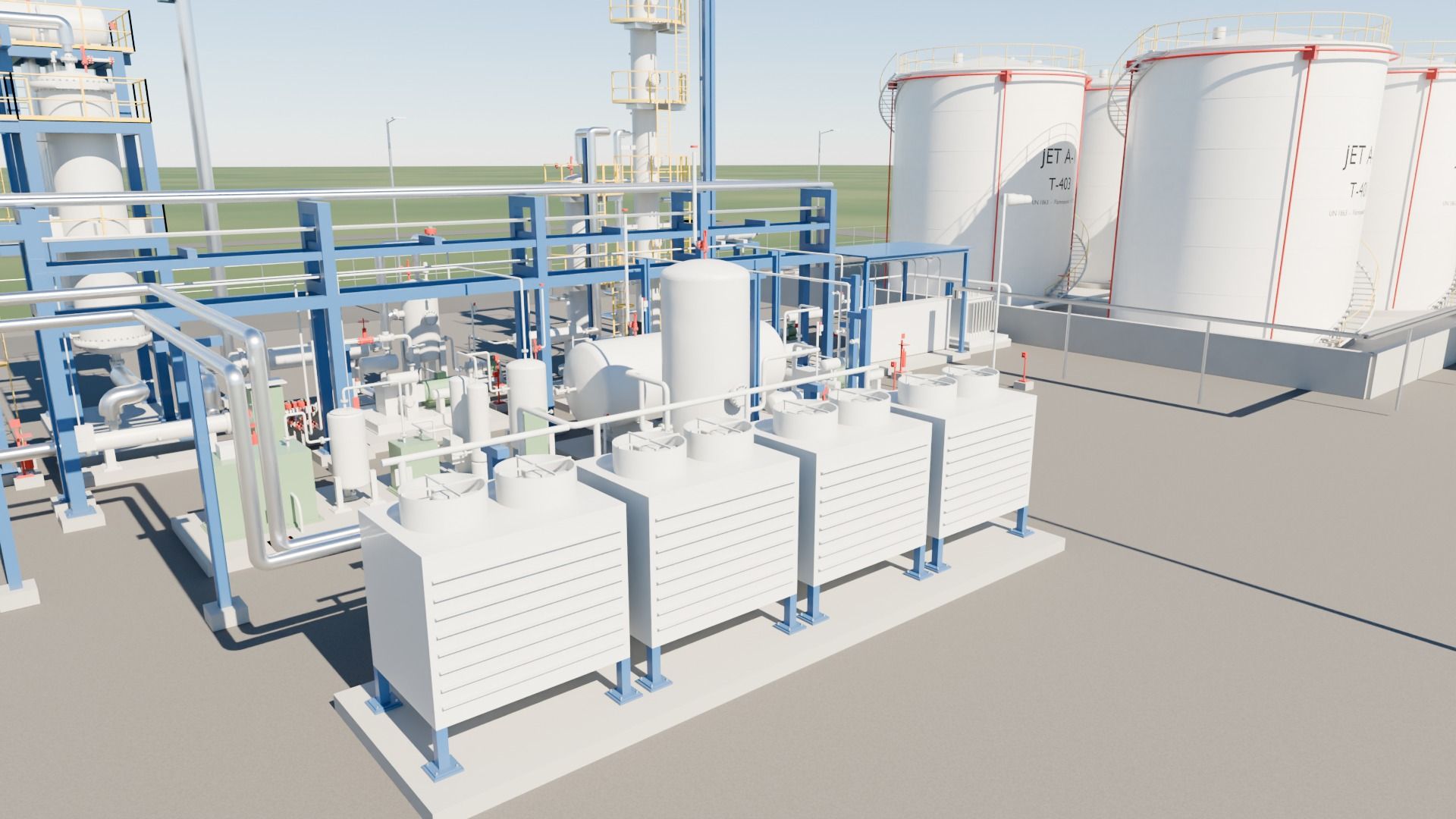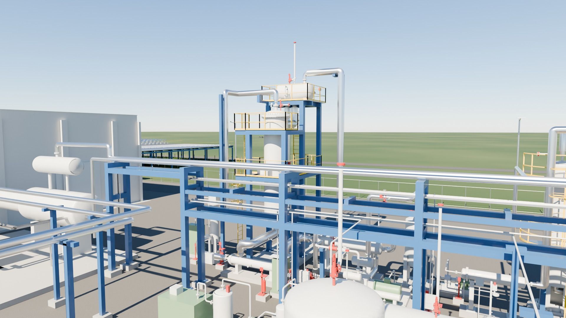
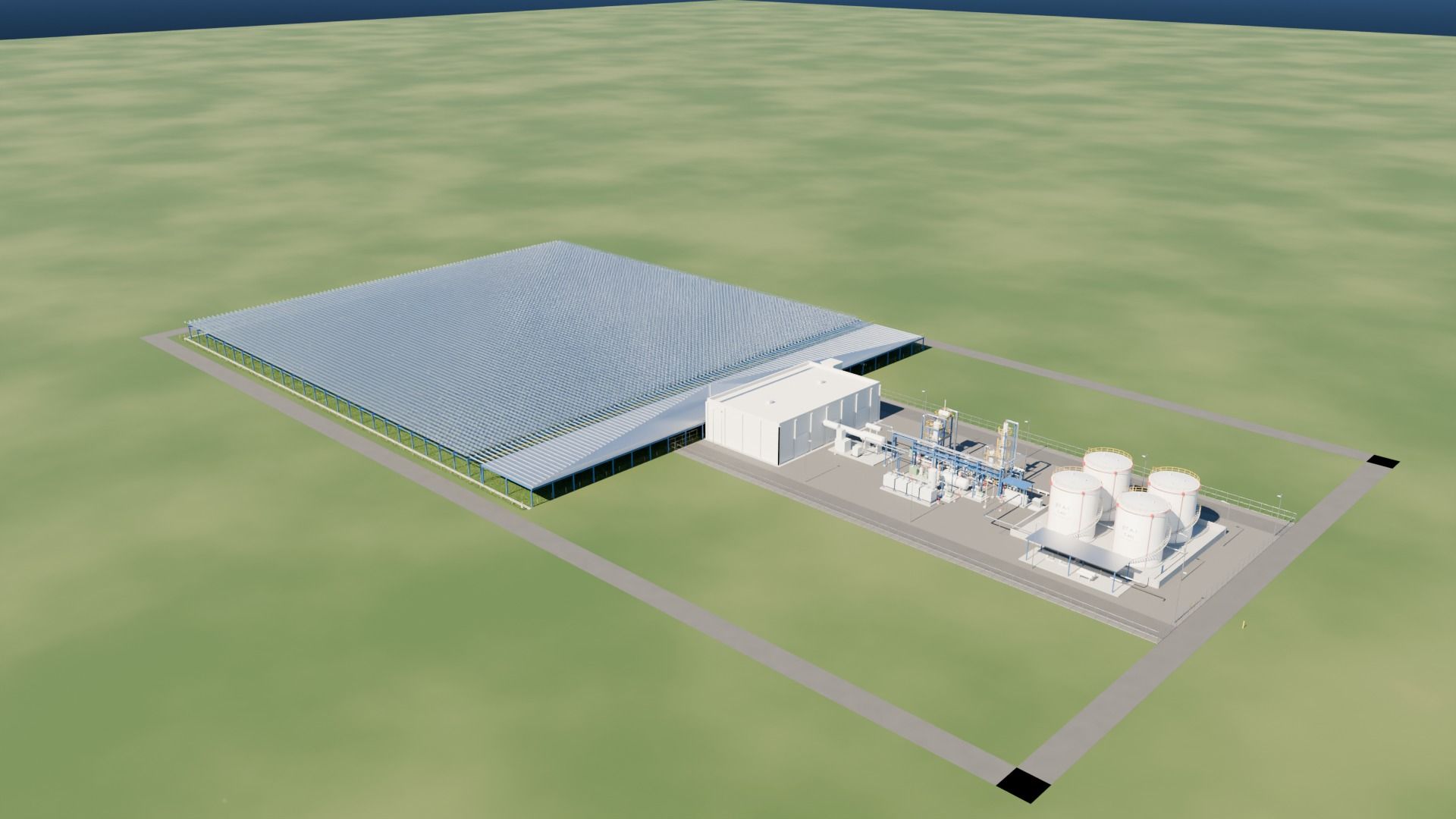
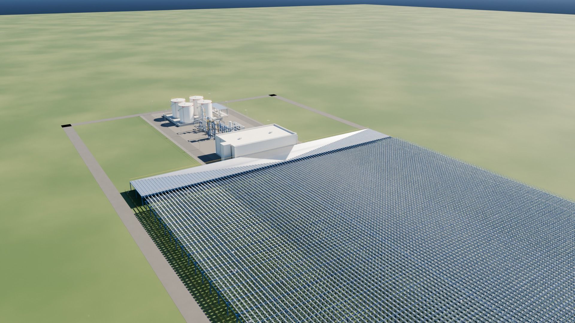
Rendering of an e-fuel production plant: halls with solar roof, process units and tank farm for synthetic kerosene

E-fuel plant engineering

Fuel Production Technologies

Fuel from sunlight, air and water

The plant

From sunlight to finished kerosene – at a single site

Our plant concept combines concentrated solar heat, CO₂ captured from the air and green hydrogen into one continuous process chain for synthetic kerosene (Jet A-1). We develop the core components ourselves.

  1. Sunlight
  2. Heat storage
  3. CO₂ from air
  4. Hydrogen
  5. Synthesis
  6. Kerosene
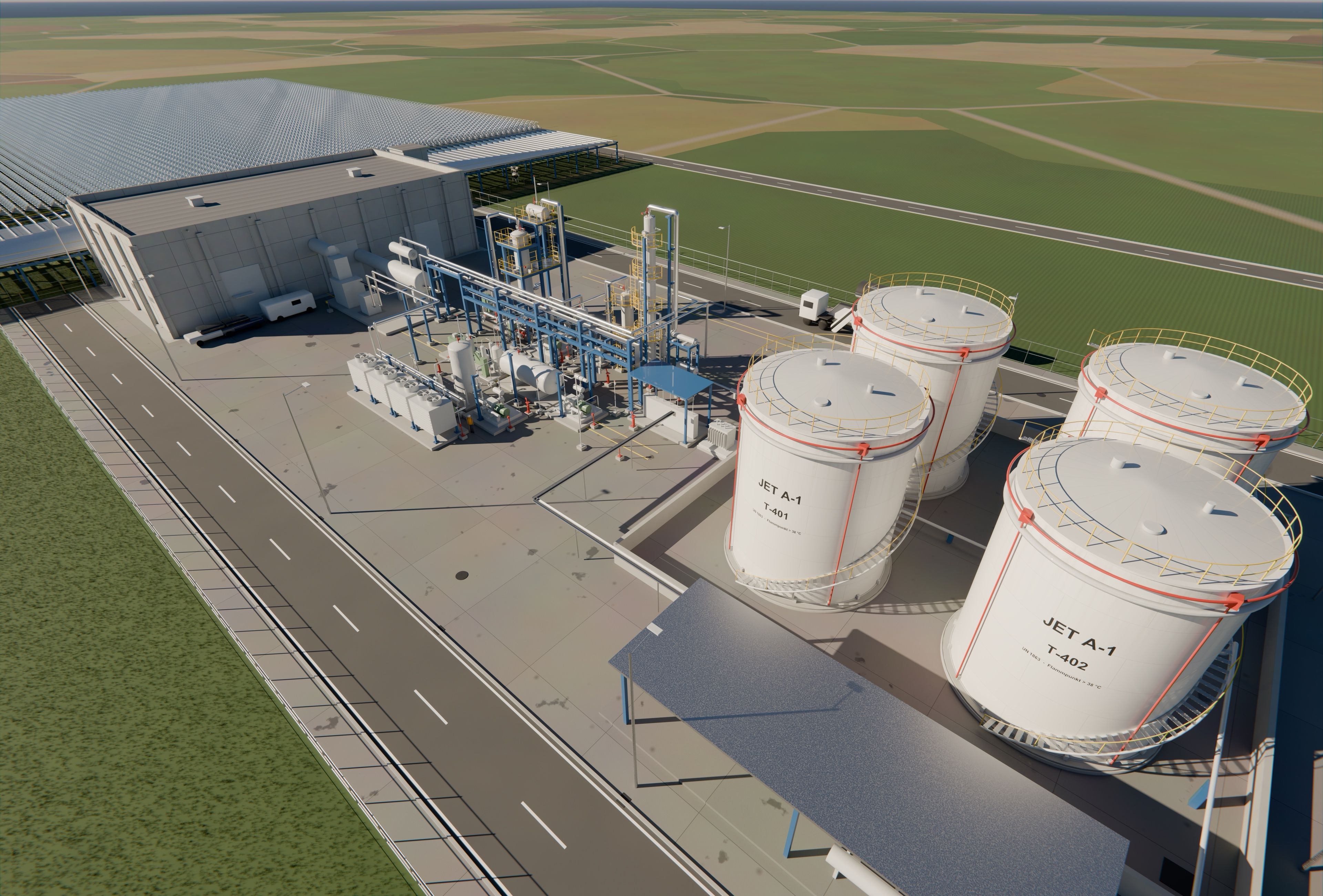
Aerial view of the complete plant: lens field, heat storage, synthesis plant and tank farm
10,000
lenses of approx. 1 m² each in the solar field
≈ 4 m
clearance – pasture remains underneath
24 × 40 × 10 m
high-temperature heat storage
3.8 M l
tank farm for Jet A-1

Computer renderings of a concept study. Dimensions, quantities and equipment are planning assumptions, not an approved or engineered plant design.

Components

The core components – developed in-house

We do not buy the key assemblies as off-the-shelf products. We design them ourselves, model them in our own CAD model and take them through to manufacturing planning. This way the components fit together precisely, and the know-how stays in the company.

Aerial view over the lens field

01Solar fieldIn-house development

Lens field

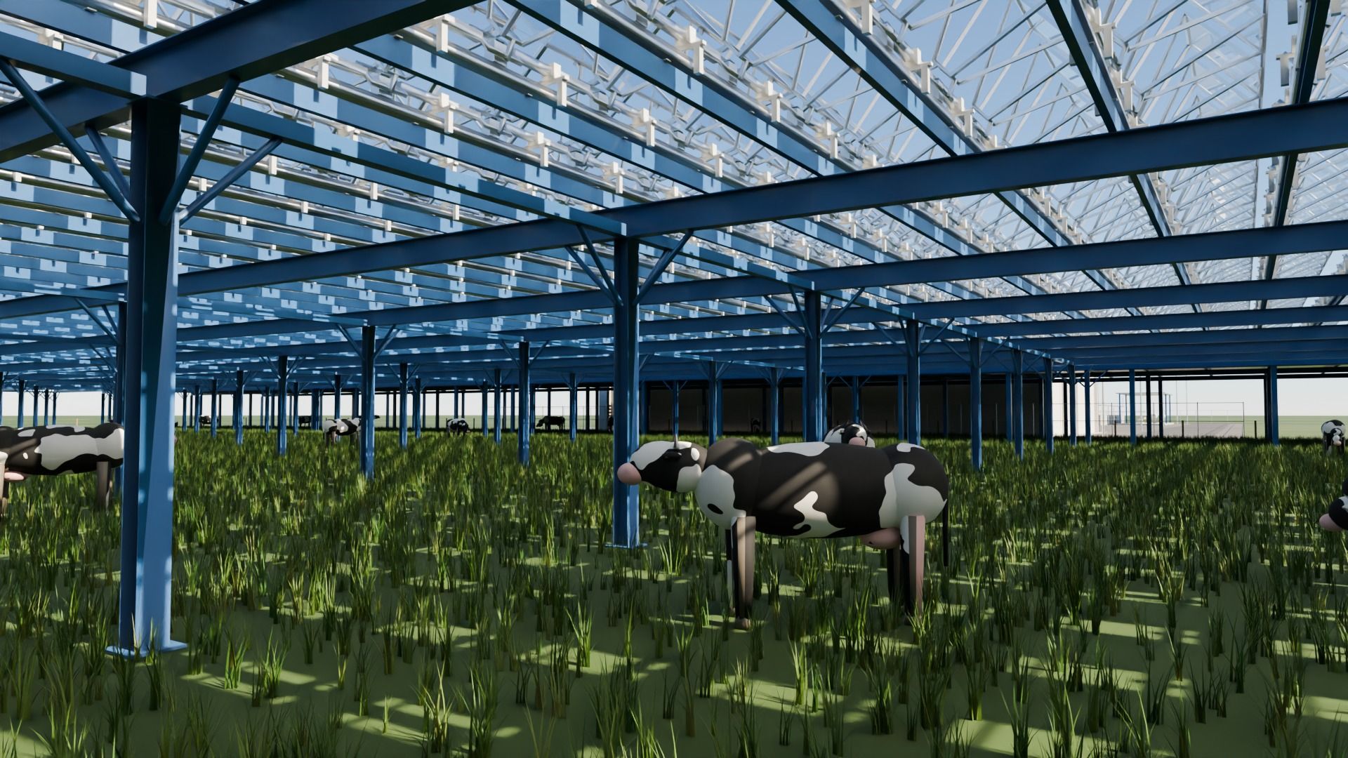
10,000 lenses of around one square metre each concentrate sunlight like a magnifying glass. They are motor-driven to track the sun and are mounted on a steel structure with around four metres of clearance – the land underneath remains available for agriculture.

  • Two-axis tracking
  • Agrivoltaic principle: pasture and energy on the same land
  • Modular row design
Light collection bridge between lens field and heat storage

02Light transportIn-house development

Optics and light channels

At the focal point of each lens, a mirror directs the light into an internally mirrored tube beneath the lens row. Through these light channels the light travels to the storage – without solar cells and without heat-transfer fluid in the field. In the light collection bridge, the 100 light tubes are bundled via deflection mirrors and led through glass windows into the storage.

  • Light instead of fluid in the field
  • Mirrored light channels
  • Light collection bridge with deflection mirrors
Heat storage with steam generator

03Energy around the clockIn-house development

High-temperature heat storage

A 24 × 40 × 10 metre structure stores solar heat at very high temperatures in rock or sand. A steam generator turns it into steam and hot water for the processes – at night and on overcast days as well.

  • Solid-media storage (rock/sand)
  • Integrated steam generator
  • Continuous plant operation
DAC modules in the foreground of the plant

04CO₂ from the airIn-house development

Direct Air Capture (DAC)

Fans draw ambient air through a sorbent that binds CO₂. Heat from our own storage releases the CO₂ again – so solar heat is used directly to obtain the feedstock.

  • Modular filter units
  • Regeneration with stored heat
  • No fossil carbon

05Green hydrogenIn-house development

Electrolyser

Placeholder: Our electrolyser produces the green hydrogen for synthesis from water. We develop the design, the stack concept and its integration into the plant’s heat and material cycle ourselves. Technical data to follow.

  • In-house stack design
  • Matched to synthesis demand
  • Heat integration into the plant
Synthesis area with reactor in the steel structure

06From gas to fuelIn-house development

Synthesis and upgrading

In the main reactor, CO₂ and hydrogen are converted directly into hydrocarbons over an iron catalyst (CO₂-based Fischer-Tropsch). A second reactor extends the molecules into the kerosene range, and the column separates the finished Jet A-1.

  • CO₂-based Fischer-Tropsch synthesis
  • Oligomerisation in a zeolite reactor
  • Distillation to Jet A-1

Our own know-how

From requirement to manufacturing file

Every component is backed by a continuous engineering chain that we built ourselves: requirements are traced across three layers, every change becomes visible down to the affected assemblies, and design ends in standard-compliant manufacturing data according to ISO 10303.

More about our Engineering Systems
Cows grazing beneath the elevated lens field
Dual land use: the pasture remains beneath the lens field.

Insights

Our plant on video

Visit our YouTube channel

Video coming soon

Privacy notice: When you click “Play”, the video is loaded from YouTube. In doing so, data (including your IP address) is transmitted to YouTube or Google, possibly also to the USA. No connection to YouTube is established before you click. Details can be found in our privacy policy.

Contact

Talk to us about your project

Whether site assessment, feasibility study or detailed plant design – we look forward to hearing from you.